Having recently acquired a Wouxun KG-699E hand-held transceiver for the 70MHz band (actually 68-88MHz PMR band) I have fitted it into the car along with a Pye A200 linear amplifier. This combination gives me roughly 25W of FM on the 4M band.
On its first outing I had a QSO with a local station who commented on the deviation being on the low side, though another local who was using his Wouxun reported no difficulty in copy. A little bit of searching on the web led me to an article by Sergey RZ3DFH which showed a microphone deviation modification for the KG-UVD1 dual band radio. With this article as my inspiration I decided to see if the KG-699 had the same type of adjustment.
First the usual disclaimer. I am unable to accept any responsibility for damage to your radio should you attempt this modification. I performed this on my own personal radio having first accepted the risk of permanent damage to the unit. I would only recommend you attempt this if you are confident working inside hand-held radios.
Step 1: Remove the battery and antenna. On the SMA connector you will see a ring nut. Carefully remove this nut and remove the power/volume knob by pulling the knob directly away from the radio. Be aware of the retaining spring clip inside the knob.
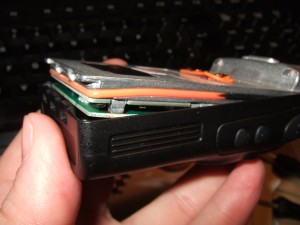
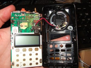
Step 2: Place the radio face down on a soft cloth and use a small flat bladed screwdriver prise the radio out of the front panel from the bottom. This is held in woth a rubber seal around the edge and gives resistance. Don’t get too rough with it. The speaker wires are soldered to the main board and speaker, but the speaker will come away from the front cover quite easily should you need to fully separate them.
Step 3: You will need to remove the keypad board from the main board. There are two screws at each side. Once the screws are out the board will still be fixed to the main board by the small multi-way connector towards the bottom left, just off centre. This will snap out with careful lifting of the bottom edge of the board.
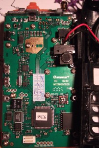
Step 4: Locate the small trimmer towards the bottom right of the main board, near the word MOD printed in white on the board. On my unit the flat side of the trimmer was facing down towards the bottom of the board. With a plastic trimming tool adjust the trimmer to the desired setting. I turned mine 180 degrees anti-clockwise and noticed a significant increase in audio on my 2nd receiver.
Step 5: Insert the keypad board again and insert the 4 retaining screws. Make sure the speaker is mounted in the front case properly.
Step 6: Carefully insert the radio back into the front cover by inserting the connector end first. Once the seals are all lined up and the buttons are all in place (don’t forget to insert the keypad button sheet if it has fallen out) then press the radio firmly back into place. Be mindful of the seals.
Step 7: Now is a good time to power up the radio and test it. My first time around I adjusted the trimmer too far and lost the contact and hence had no audio. Once you are happy then put the SMA nut back on and tighten up. Replace the volume knob, being careful not to bend the retaining screw out of shape. Getting the knob back on took me more time than the modification!
Step 8: Enjoy being able to be heard on 4M a bit better. I did notice that the radio does not have a hole directly in front of the microphone insert. I decided against drilling a new hole as with the deviation modification performed the audio from the internal microphone seemed better too.
Note: I did not remove any components as suggested by the linked article above. As the boards are very different I decided not to risk trying to identify them.


